- Other Truck Parts[7]
- Pumps[10]
- Fuel Systems[5]
- Speed Reducers[5]
- Gearboxes[2]
- Contact Person : Ms. Yu Candice
- Company Name : Shanghai Youhuan Transmission Machinery Co., Ltd.
- Tel : 86-21-66580117
- Fax : 86-21-56555311
- Address : Shanghai,Shanghai,Floor 1901,No12 Building,#938 Datong Road,Zhabei District
- Country/Region : China
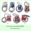
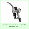
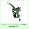
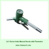
Electronic manual nozzle with flowmeter
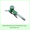
Electronic manual nozzle with flowmeter
I. Usage
DLY series of electronic nozzle with flowmeter (abbreviated as oil-filling gun) is a meter used to measure the volume flow rate of liquid passing through the pipe. It is suitable for measuring gasoline and kerosene fuel etc. The meter has such advantages as high accuracy and convenient and flexible use. As long as there is a height difference of 2m to 10m between the liquid level of measured medium and the meter, it can operate normally without any additional power source.
II. Main technical parameters
1. Nominal diameter and flow rate:
Model | Nominal diameter (mm) | Minimum Flow rate (L/min) | Rated flow rate (L/min) | Maximum flow rate (L/min) | Display value of meter | Accumulated value |
DLY-25 model | 25 | 25 | 35 | 60 | 0.1~9999.9 | 0.1-9999999.9 |
DLY-32 model | 32 | 32 | 50 | 100 | 0.1~9999.9 | 0.1-9999999.9 |
DLY-38 model | 38 | 32 | 65 | 120 |
0.1~9999.9 |
0.1-9999999.9
|
2. Metering accuracy: ±1%
3. Measured medium: gasoline. If the medium is kerosene or diesel oil, the readings of flow meter shall be corrected. Refer to article 5 of clause 4 for details.
4. Maximum working pressure: 0.1MPa
III. Main structure and working principle
The electronic nozzle with flowmeter is composed of electronic digital displayer, metering chamber and main body etc. three parts. Among them, the electronic digital displayer is composed of magnetic coupler, accumulation indicator and zero-resetting device etc. mechanism. The metering chamber is composed of core rack, impeller, worm wheel and worm. The main body is composed of meter shell, oil inlet and outlet tank and valve mechanism etc.
Grasp firmly the bending handle. When the valve opens, the liquid will pass through the oil tank and flow into the metering chamber, and under the action of liquid, the impeller will produce torque to rotate. The rotation speed of impeller will be reduced by worm wheel, worm and gear, and driven by the magnetic coupler, the electronic digital displayer will carry out calculation, so that the volume quantity of liquid passing through the pipe can be read out.
1. Oil inlet pipe
2. Rubber cushion
3. Orifice plate rectifier
4. Core rack
5. Impeller
6. Meter cover
7. Electronic digital displayer
8. Battery
9. Sensor
10. Magnetic coupler
11. Worm wheel
12. Valve mechanism
13. Oil outlet pipe
14. Bending handle
15. Gun
16. Adjuster
Structure of digital displayer
Flashing display in case of insufficient power
Display screen
Display value on display screen
Zero-resetting
After pressing it continuously for 12 seconds, the accumulated display value will automatically reset to zero.
Switch
Meter cover
Auxiliary switch of power supply
Sensor
Battery box
I. The display screen is of liquid crystal display.
II. The display value on the top of the screen is the latest reading.
III. The display value on the bottom of the screen is the latest reading.
IV. Press once the zero-resetting device, the latest display value will reset to zero. Press it continuously for 12 seconds, the accumulated value will reset to zero.
V. The switch is power supply switch of battery.
VI. Power supply display: if flashing display occurs under the situation of insufficient power, the battery shall be replaced.
VII. Auxiliary switch of power supply, sensor and battery box.
IV. Detailed rules for use and installation
Before installation, the liquid transporting pipe and rubber hose shall be cleaned, and then connect the rubber hose with the pipe connector of electronic nozzle with flowmeter and fasten it to start the use. DLY-25 model or DLY-32 model indicates that rubber hose with inside diameter of Φ25 or Φ32 can be used for connection.
1. The flow value of measured medium in the pipe shall be within the flow range stipulated by the metering oil-filling gun. Refer to article 1 of clause 2 for details.
2. The liquid level of measured liquid shall be 2-10m higher than the flow meter.
3. The metering oil-filling gun shall be installed with “filtering device” at its front so as to guarantee the cleanliness of liquid. The “filtering device” can adopt steel wire cloth of at lease 20 meshes, and the total area shall be more than 75mm for filtering the liquid.
4. The metering oil-filling gun is a relatively precise meter, which is forbidden to be knocked or beaten. In case of any malfunction of the meter, please first get familiar with the structure, then carry out sequential disassembly and inspection carefully, and calibrate and check again after the disassembly.
(1) The precision of standard vessel shall not be less than ±0.2%.
(2) When calibrating, select low, middle and high etc. three points within the flow range of the meter and carry out test thrice at each point, then take the average value.
The metering precision of meter shall be calculated according to the following formula:
E= Vmeter-Vstandard ×100% In the formula: Vstandard E --- metering precision Vmeter --- display value of meter Vstandard --- display value of standard vessel |
During the calibration, if it is necessary to adjust the meter precision, please disassemble the lead seal, remove the screw of lead seal, then screw off the fastening screw, and screw in the adjusting screw, which is positive, and screw out the adjusting screw, which is negative. After the adjustment assemble them in turn, and the meter after the calibration shall meet the requirements of precision.
5. The oil-filling gun is velocity type meter so the change of viscosity and density of medium will affect the display value of meter. When leaving the factory, the gasoline (or simulated gasoline) is used as calibrating medium. Therefore, when measuring kerosene or diesel oil, the display value of meter shall be corrected. If the condition permits, users shall calibrate it again under the working condition. The viscosity of kerosene may be greatly affected by the temperature, hence, difference may exist in the corrected coefficients under different temperatures. The corrected coefficients deducted after experiment will be recommended to users.
The calculation formula is as follows:
Actual oil filling amount: corrected coefficient×display value of flow meter (liter)
Corrected coefficient: (1) If the medium is kerosene, the corrected coefficient equals to 0.994.
(2) If the medium is diesel oil and the oil temperature is more than 10°C, the corrected coefficient equals to 0.978.
If the medium is diesel oil and the oil temperature is less than or equal to 10°C, the corrected coefficient equals to 0.957.
(Application instance): when measuring the diesel oil, the oil temperature is 13°C, the display value on the meter panel of oil-filling gun is 150 liters, what is the actual oil filling amount?
Actual oil filling amount=0.978×150 liters=146.7 liters
Answer: the actual oil filling amount is 146.7 liters.
6. Installation figure
Electronic manual nozzle with flowmeter